

How To Remove Shock Bushings
Eyelet Hardware Maintenance
Alarm: Fox products should be serviced by a qualified bicycle service technician, in accordance with Fox specifications. If you have any uncertainty whether or not you can properly service your Flim-flam product, then DO NOT effort information technology. Improperly serviced products can fail, causing the rider to lose control resulting in SERIOUS INJURY OR Expiry.
There are 5 styles of eyelet hardware for FOX shocks: 2-piece reducer, three-slice pin and sleeve, five-piece flanged bushing, Bearing Mounting Hardware, and vii-piece Vanquish Washer Hardware.
Click the photo beneath that best matches your eyelet hardware setup to view its service procedure.


Your rear shock eyelet hardware should always provide a snug fit between your shock and bike frame. When excessive play develops, this status tin can lead to costly harm to your shock eyelets if not serviced accordingly. Preventative maintenenace of the eyelet hardware can help forbid damage to your shock.
2-Piece Reducer
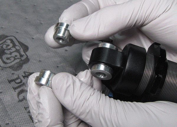
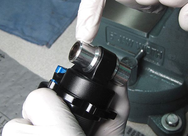
The ii slice reducer hardware assembly is made upward of two reducers, pressed into either side of a DU bushing that is pressed into the shock eyelet.
Step i
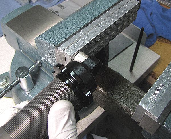
Utilise a standard bolt extractor (EZ-Out or similar) to remove the two reducer pieces. Press the bolt extractor into either reducer with a counter-clockwise twisting motion, then pull while standing to twist counter-clockwise to remove. Repeat for the 2d reducer.
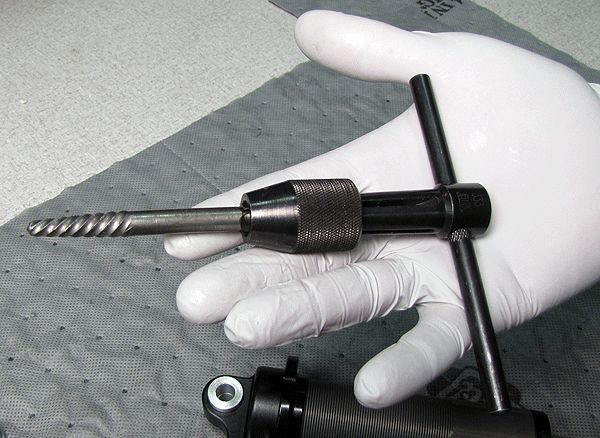
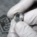
Step 2
Remove the reducer from the commodities extractor by gently clamping the reducer and rotating the tool clockwise. If planning to reuse the reducers, brand sure to avert clamping them also tightly in your vice to keep them round.
If your reducers fit tightly in your DU bushings and remain circular afterwards removal, they can be reused. Small internal marks on the reducers from the bolt extractor are fine.
For data guiding you through the replacement of the DU bushings in your shock eyelet, please go to: DU Bushing Replacement »
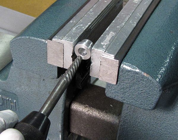
Pace 3
Starting time pressing the reducers into the new DU bushing by hand. Use a soft-jawed vice to fully seat the reducers in the DU bushing.
3-Slice Pin and Sleeve
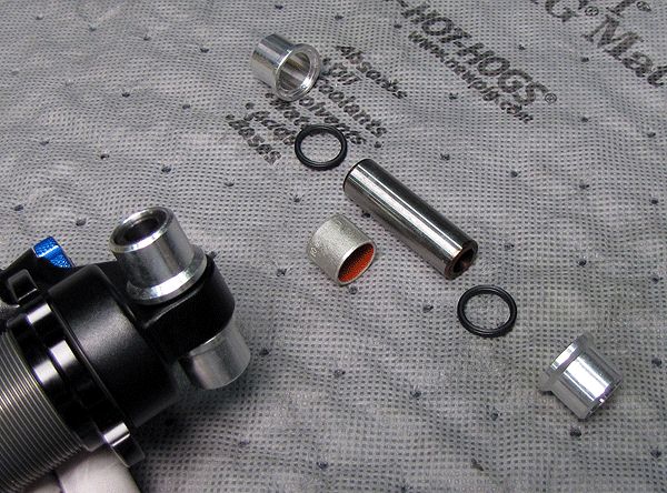
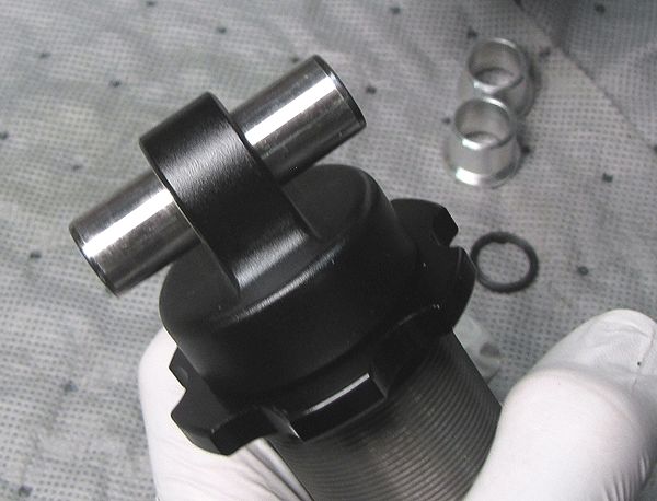
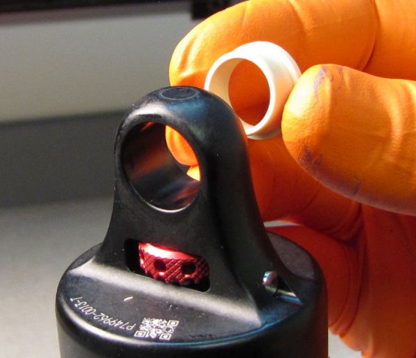
The iii-piece pin and sleeve assembly is made up of a single hollow pin that is pressed through the DU bushing in the stupor eyelet. The two sleeves mount over the pin from either side and keep it centered. Q-rings are located betwixt the sleeves and the daze eyelet to prevent contamination and premature DU wearable.
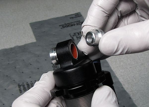
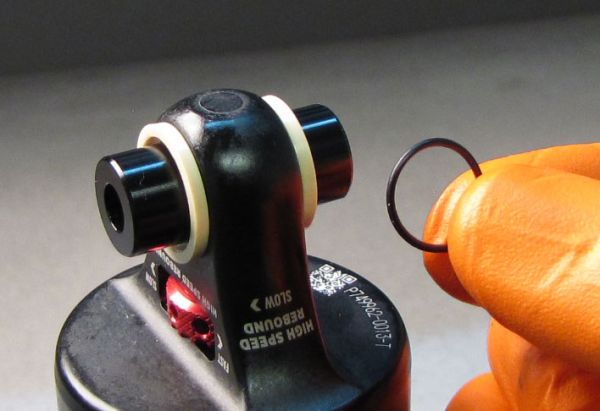
Step 1
Remove both sleeves by pulling them away from the stupor eyelet. Remove the 2 Q-rings.
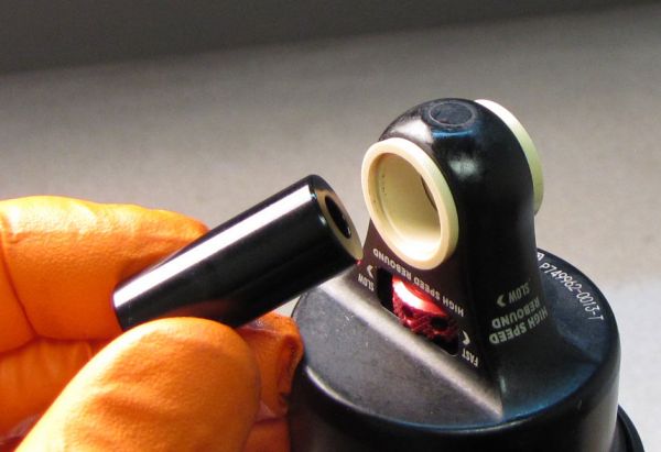
Step 2
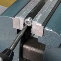
Apply a soft-jawed vice to push the pivot every bit far out through one side of the shock eyelet equally possible.
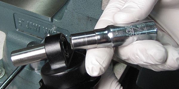
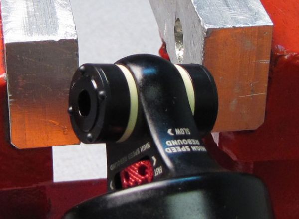
Step iii
Employ a soft-jawed vice and a socket small enough in diameter to pass through the DU bushing, to push the pin the rest of the style out.
For data guiding y'all through the replacement of the DU bushings in your shock eyelet, delight get to:DU Bushing Replacement »
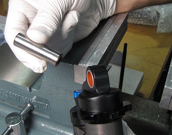
Step four
Commencement pressing the pin into the new DU bushing with your soft-jawed vice.
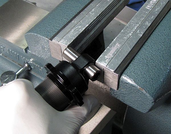
Footstep 5
Reposition your shock in the soft-jawed vice so 1 side of the eyelet is resting confronting the vice jaw. Go along to press the pin into the DU bushing until the shock is centered on the pin.
Step 6
Utilise the 2 sleeves to verify that the pin is centered in the shock eyelet. Remove the sleeves, install the Q-rings, then reinstall the sleeves.
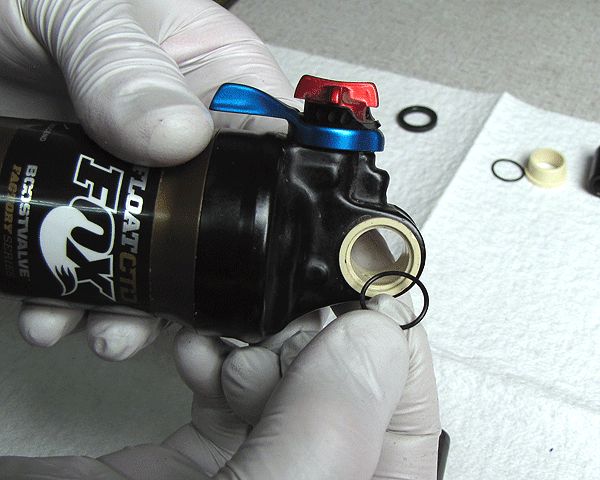
v-Slice Flanged Bushing
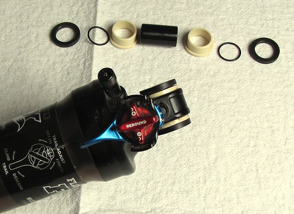
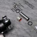
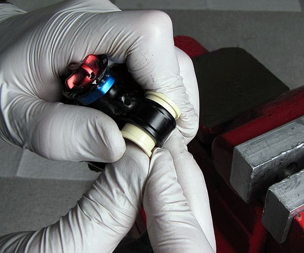
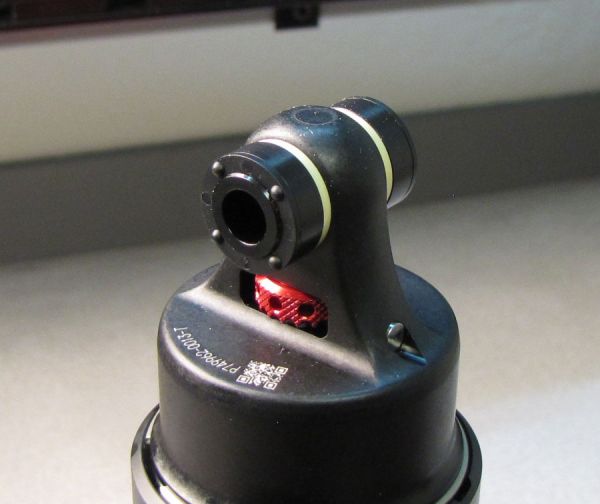
The v-piece flanged bushing eyelet hardware assembly is made up of 2 beige colored flanged bushings that are pressed into the stupor eyelet. A hollow pin is pushed through the flanged bushings and centered by black Delrin spacers on either side of the eyelet. Sparse o-rings go betwixt the spacers and flanged bushings to prevent contagion and premature bushing wear.
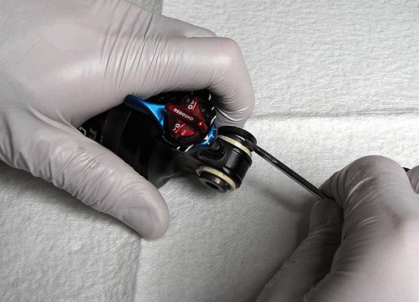
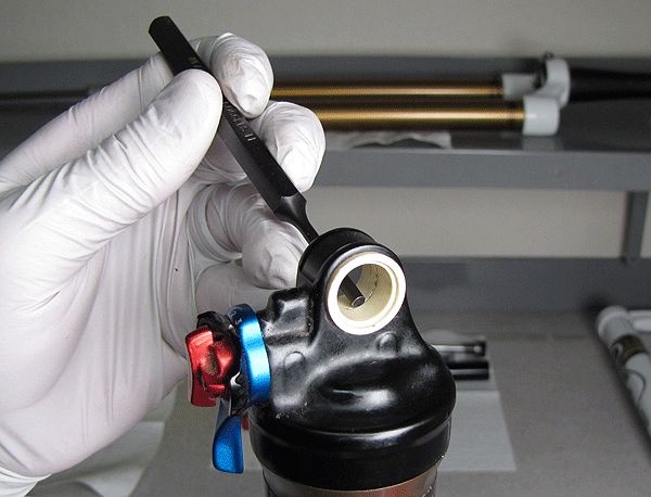
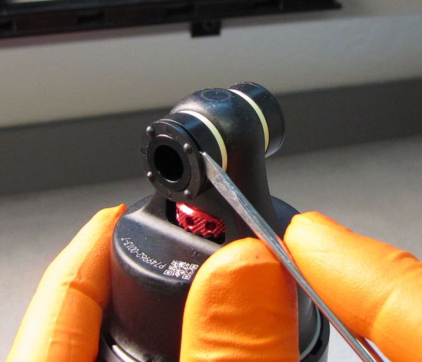
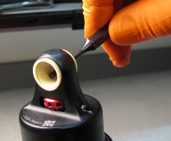
Footstep 1
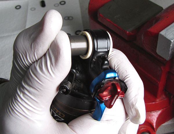
Carefully remove the blackness Delrin spacers with a pocket-size flat driver.
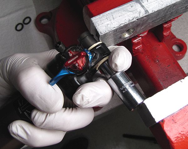
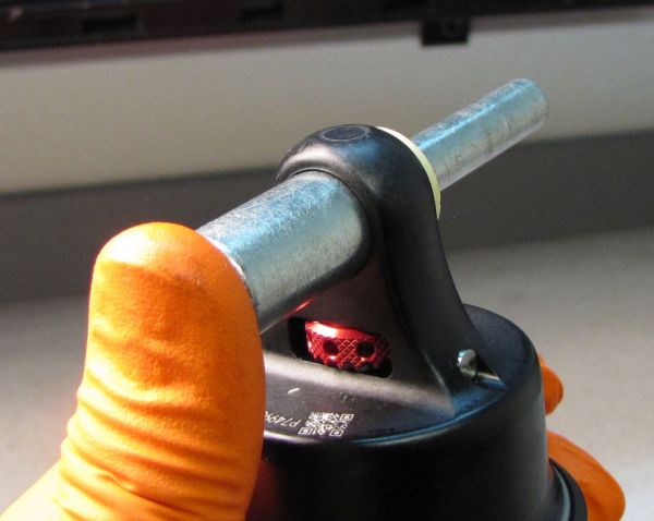
Footstep 2
Use a socket and your soft-jawed vice to push button the pin out of the flanged bushings.
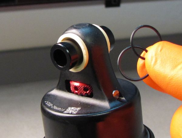
Footstep three
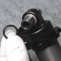
Remove the o-rings and replace if necessary.
Stride 4
Apply a small dial or other similar tool to drive out the flanged bushings from the center. Back up the stupor with your hand during the bushing removal.
Step five
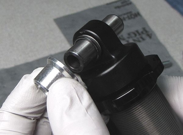
Y'all tin can apply part of the DU bushing removal tool (PN: 803-00-046-A) to help remove the second flanged bushing from the shock eyelet.
Step six
Start installing the new flanged bushing by hand, then finish with your soft-jawed vice. Exist careful not to press the bushings in with likewise much vice clamping force to avoid harm to the new bushings.
Step vii
Outset installing the pivot into the flanged bushings by hand and finish with your soft-jawed vice. Center the pin in the shock eyelet.
Step 8
Install an o-band into the recess in each flanged bushing, then install the black Delrin spacers.
Bearing Mounting Hardware
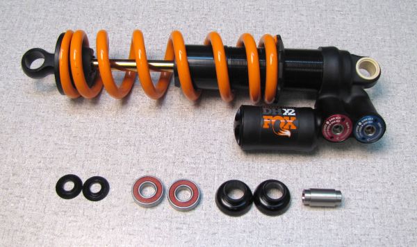
The Bearing Mounting Hardware assembly is made up of ii black Bearing Housings that are pressed into the shock eyelet. Ii Roller Bearings are pressed into the Bearing Housings with a silver Bearing Spacer trapped between the 2 Bearings. Black Begetting Spacers proceed the outside of the Bearings to middle the assembly and preclude contagion.
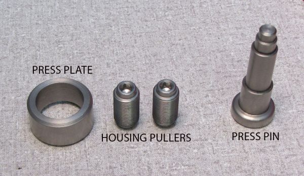
Yous volition need the Mounting Hardware Begetting Associates Install and Removal tool (PN: 803-01-406) to remove this mode hardware once installed.

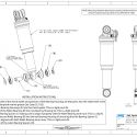
Bearing Mounting Hardware is only available for certain applications and is only compatible with the stupor eyelets listed in the chart.
Note: 2022-2021 X2 shocks all accept the same restrictions apropos eyelet and Bearing Hardware compatibility. Please run into the chart for details.

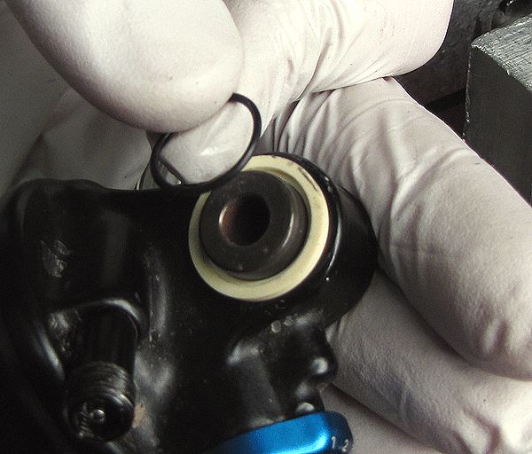
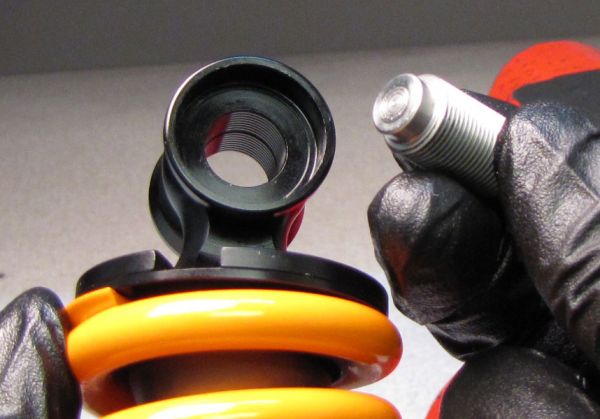
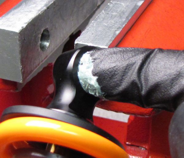
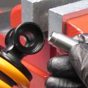
Step 1
Remove the 2 blackness outer Begetting Spacers. Insert the Press Pivot tool into one Roller Begetting while resting the reverse Bearing Housing in the Printing Plate equally shown.
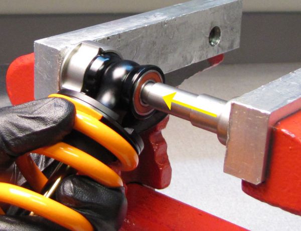
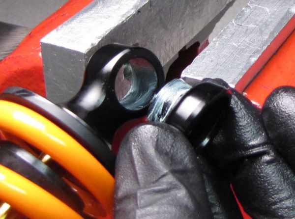
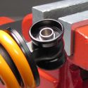
Step 2
Squeeze the Press Pin and Press Plate together in your vise to remove the first Roller Bearing. Take care non to damage any portion of the shock by allowing information technology to contact the vise. Afterwards pressing out the showtime Roller Begetting, remove the argent Bearing Spacer.
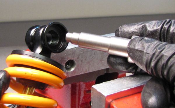
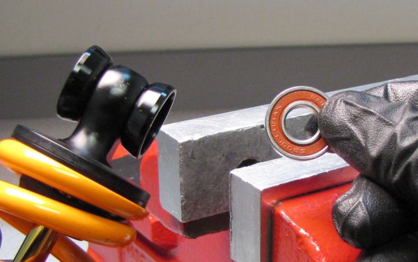
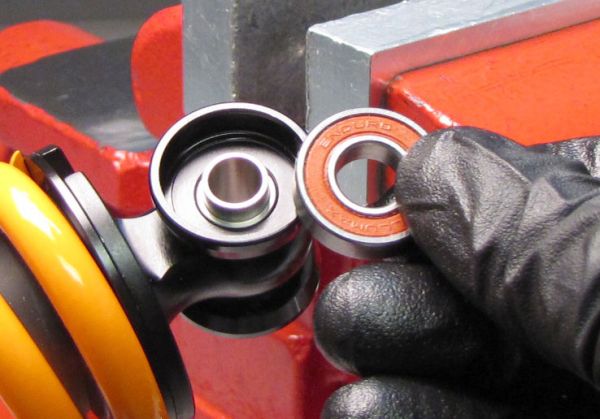
Pace 3
Reinsert the Printing Pin tool into the empty Bearing Housingwhile resting the contrary Bearing Housing in the Press Plate equally shown.Squeeze the Press Pin and Press Plate together in your vise to remove the second Roller Bearing.
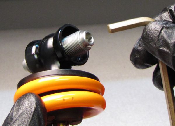
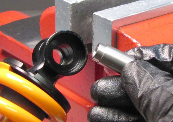
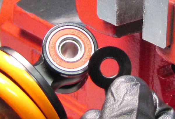
Pace 4
Thread one of the Housing Pullers clockwise into an empty Bearing Housing then the hex characteristic faces out, away from the eyelet. Thread the 2nd Housing Puller clockwise into the other empty Bearing Housing. Suit the Housing Pullers with a 5mm hex wrench until they are centered and touching eachother.
Step v
Utilize a 5mm hex wrench to turn one of the Housing Pullers clockwise until you lot take pushed the opposite Bearing Housing out of the eyelet. Remove the Housing Puller tool from the Bearing Housing that y'all've only removed.
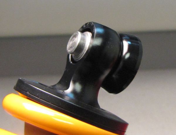
Step half dozen
Accommodate the tool remaining in the eyelet then the shoulder below the 5mm hex feature is flush with the inside of the Bearing Housing equally shown. With a plastic faced mallet, carefully strike the solid end of the Housing Puller tool to bulldoze the remaining Bearing Housing out of the eyelet. Do non remainder whatsoever portion of the shock on any surface while applying conscientious mallet strikes.
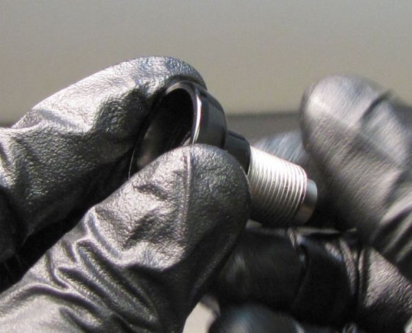
Step seven
Remove the tool from the Bearing Housing.
Step 8
The following steps guide you through the installation of the Bearing Mounting Hardware.
Coat the inside of the shock eyelet bore and the portions of the Bearing Housings that press into the eyelet with a thin film of waterproof marine grease (Sta-Lube SL3125).
Step 9
Install both Bearing Housings into the shock eyelet past carefully pressing in with a soft-jawed vise.
Step 10
Install one of the Roller Bearings into one of the Bearing Housings past carefully pressing it in with a soft-jawed vise.
Footstep 11
Install the Bearing Spacer through the empty Begetting Housing, making sure to marshal information technology properly with the installed Roller Bearing inner race.
Step 12
Install the second Roller Bearing into the empty Begetting Housing ensuring that the Bearing Spacers is properly aligned between both Roller Begetting inner races. Press the 2d Roller Bearing in with your soft-jawed vise.
Step thirteen
Install the Outer Bearing Spacers with their protrusions aligned with the Roller Bearing inner races. You can utilise a zip-necktie to concord everything together until installing onto your cycle.
vii-Slice Crush Washer Hardware
Step i
The vii-slice Crush Washer eyelet hardware assembly is fabricated up of ii beige colored flanged bushings that are pressed into the shock eyelet. A hollow pin is pushed through the flanged bushings and centered past black Delrin spacers and Crush Washers on either side of the eyelet. Thin o-rings go betwixt the spacers and flanged bushings to forbid contamination and premature bushing wear. The Shell Washers have raised domed portions that are depressed before installation and take up whatever play found between frame and hardware.
Stride ii
Carefully remove the Beat Washers and blackness Delrin spacers with a minor flat driver.
Stride 3
Remove the two o-rings then push the pivot out of the flanged bushings. You may use a socket or other tool to push the pin out if you cannot do it with mitt pressure level alone (DU removal tool shown PN: 803-00-046-A).
Step 4
Apply a small-scale punch or other like tool to drive out the flanged bushings from the center. Support the stupor with your hand during the bushing removal.
Footstep 5
You lot can use office of the DU bushing removal tool to help remove the second flanged bushing from the shock eyelet.
Footstep 6
Start installing the new flanged bushing past mitt, then end with your soft-jawed vice. Exist conscientious not to printing the bushings in with too much vice clamping strength to avert impairment to the new bushings.
Step 7
Start installing the pin into the flanged bushings past hand and terminate with your soft-jawed vice. Center the pin in the shock eyelet.
Step viii
Install an o-ring into the recess in each flanged bushing, then install the blackness Delrin spacers followed by the Beat Washers with thier domed protrusions facing out.
Step ix
Use your soft-jawed vise to shrink the domed protrusions of beat washers. Tighten the vise fully as it will finish when it hits the Pin. Remove the completed eyelet hardware assembly from the bike and so install onto the bike.
DU Bushing Replacement
Step 1
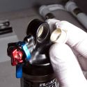
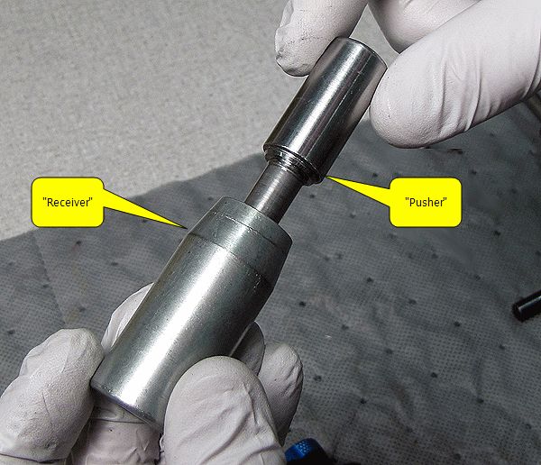
The DU Removal tool (PN: 803-00-046-A) is made up of a pusher and a receiver.
-m.jpg)
Step 2
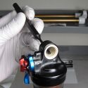
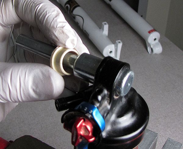
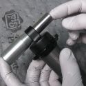
Insert the pusher portion of the DU removal tool through the DU bushing in the shock eyelet. Install the receiver portion of the DU removal tool onto the exposed portion of the pusher.
-t.jpg)
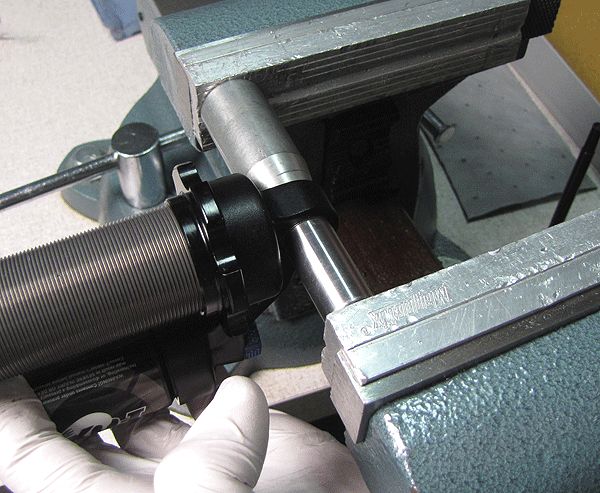
Pace 3
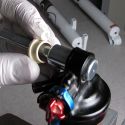
Use your soft-jawed vice or a press to squeeze the ii ends of the DU removal tool together until the DU bushing is driven out of the eyelet and into the receiver portion of the DU removal tool.
Stride 4
Install a new DU bushing by pressing information technology into the stupor eyelet with your soft-jawed vice or press.
Dealer, Distributor, and OEM access
© FOX Manufacturing plant, Inc. 2022
1.800.FOX.SHOX

How To Remove Shock Bushings,
Source: https://www.ridefox.com/fox17/help.php?m=bike&id=251
Posted by: priceforomed.blogspot.com
0 Response to "How To Remove Shock Bushings"
Post a Comment